Szívócsatorna méretezés

Of all the aspects of intake manifold design, the bellmouths are particularly mysterious, perhaps because most do-it-yourself builders, and even many businesses, simply do not have the technical or financial resources to conduct tests of bellmouth performance. Building a single custom intake manifold is a big enough task, let alone repeating it three or more times. For that reason, velocity stack style and placement are hotly contested topics on forums and bulletin boards. Luckily, commercial Computational Fluid Dynamics (CFD) software packages can unravel mysteries like this.Our engineering department at Integrated Engineering is equipped to resolve some aspects of the bellmouth controversy.
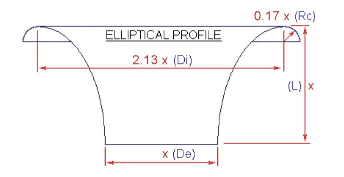
This article will consider several styles of inlets, as shown in Figure (1). The first type,(A), is a full radius bellmouth with an optimized curvature and a generous radius on its outside diameter. This is what IE uses in its intake manifolds. The second example, type (B), has the same optimized inner curvature as type (A). However, it is installed flush with the plenum floor, eliminating the possibility of a bellmouth radius. The last type, (C), is very common because it is simple to fabricate. In this case, there is a basic radius, 1/2" on the lip of the runner as it meets the plenum floor. All the examples here will be "installed" using CFD simiulation into a virtual plenum with ample volume for even airflow regardless of the inlet style. For the purposes of this study, all runners will have a 48mm inside diameter and measure 150mm from plenum to runner exit. They will be tested with a pressure differential equivalent to the 28" standard used on commercial flow benches. A surface finish representative of cast aluminum is assumed in all cases.
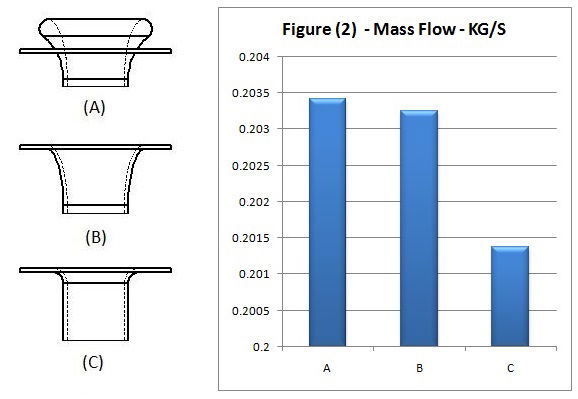
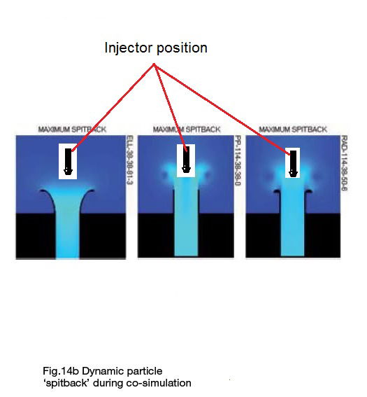
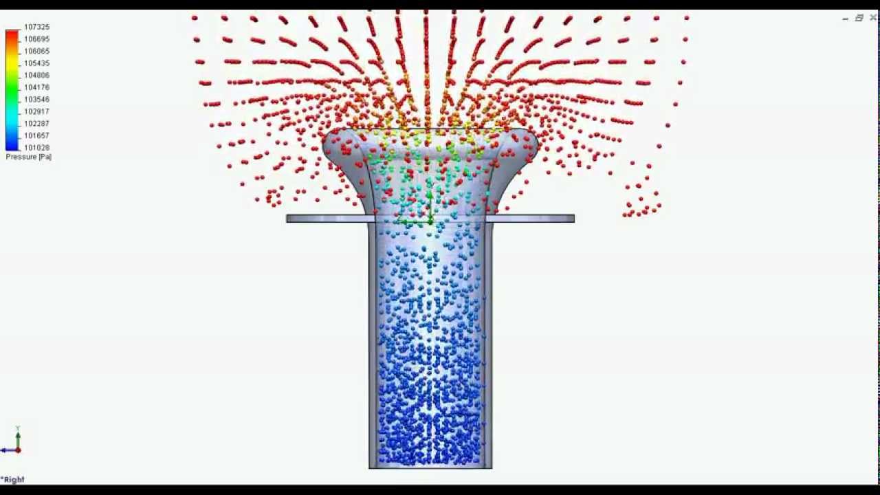
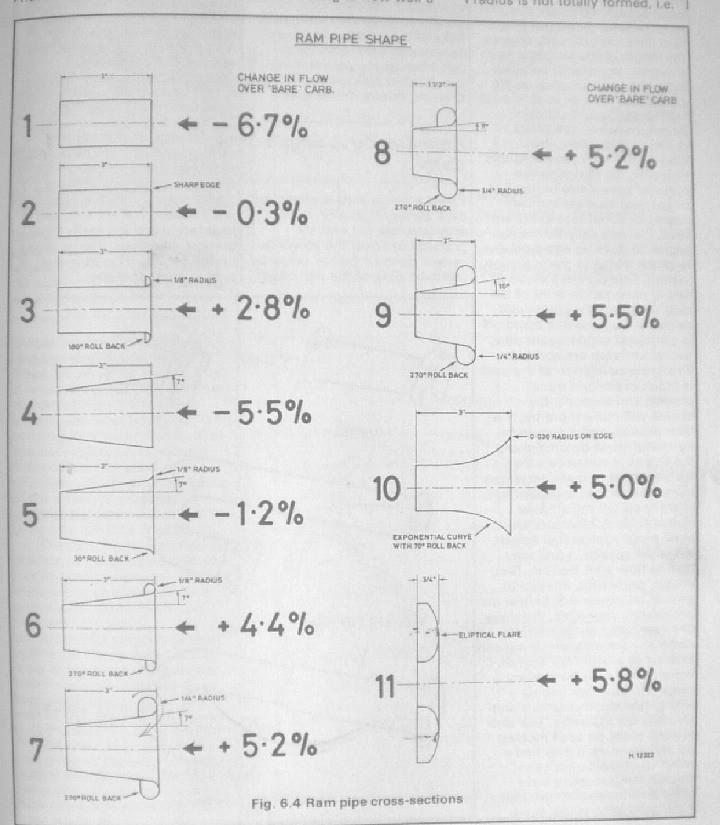
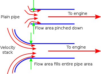
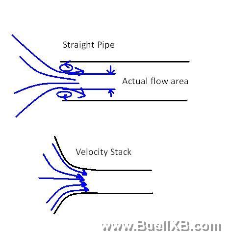
Results: The results are shown in Figure (2). As indicated, the raised bellmouth, type A, provides the highest available flow rate by a slight margin. Type B, the flush mounted bellmouth, also provides a high level of performance. Type C, with its simple radius, is the lowest performing inlet type tested by a comparatively large margin. However, even this margin only represents a change of approximately 1%- perhaps 4 to 5 horsepower on a turbocharged street engine. The raised bellmouth is more efficient for several reasons. The task of a bellmouth manifold is to effect a transition from the slow moving airflow in a large plenum to the fast moving airflow in a small tube. As shown in Figure (3), the simple radius inlet style creates a large cushion of low pressure air immediately trailing the inlet on either side. This effectively chokes down the tube diameter at this point. The high velocity gasses flowing in the center never properly recover, and the effective area of the tube is reduced. Given the fixed pressure drop, this equates to lower air (mass) flow rates. Also take notice of the uneven dip in pressure at the center of the inlet, another symptom of the uneven airflow distribution caused by this style of inlet. In Figure (4), you can see the optimized bellmouth inlet used in our intake manifolds. Notice the even distribution of pressure across the inlet. Also notice how the two characteristic high pressure zones seen on either side of the entrance on figure (3) are not present in the bellmouth radius design. The bellmouth makes the best use of the available diameter and creates the most airflow. Finally,Figure (5) demonstrates the same optimized bellmouth installed in a raised position. Even here, the bellmouth works more efficiently than the other designs. The air wraps up and around the generous radius on the edge of the bellmouth, more smoothly following it's contours. The large radius on the outer edge of the raised radius contributes most to the small increase in flow between it and the flush mounted installation. Finally, the raised bellmouth allows air to wrap in from farther around, rather then frm a simple 180 degrees. The light blue areas show the airflow wrapping up and around the large radius on the outer edge. Please see Video (1) below. Contrast that to Figure (4), where you can see the bright blue is directly touching the cast aluminum floor of the plenum.

1. IE CFD Study of Optimized Raised Inlet
2. CFD Study of an optimized bellmouth - flush mounted
3. CFD Study of 1/2 Inch Radiused Inlet
Conclusions: Manifold design is an important feature for a performance engine designed to extract every last possible horsepower.This study shows that a properly optimized bellmouth manifold delivers measurable and significant gains over a simple radius. For that reason, every Integrated Engineering intake manifold features carefully optimized bellmouth inlets. A raised bellmouth can also be advantageous, provided the plenum is large enough to allow sufficient airflow over and around the raised inlets. This style should not be used with smaller plenum designs. In some IE intake manifolds, this design is also used in conjunction with a properly tuned length runner where overall space constraints would not otherwise allow it. The raised bellmouth design allows a longer runner to be used in smaller spaces. These factors, combined with the manufacturing complexity of raised bellmouths, explain why many OE applications do not utilize them, and they are typically seen only in high end motorsport applications.




Forrás: https://performancebyie.com/blogs/ie-auto-blog/the-right-bellmouth


